Phone and Network Cables

We will use "CAT-5" for the phone, network and ISDN runs. This page discusses the wiring for these services. The topics covered here are:

CAT-5 Cable

"CAT-5" is a nickname for cable with four wire pairs that each meet the "Catagory 5" specification for data communications. The specification defines the conductor size, insulation quality and wire twists, plus a multitude of performance characteristics. In theory, all CAT-5 cables perform the same, supporting data transmissions up to 100MB/s. A more stringent cable specification is "Catagory 6" ("CAT-6"), supporting data transmissions up to 1GB/s. A less stringent specification is "Catagory 3" ("CAT-3"), supporting data transmissions of only 10MB/s or less.

CAT-5 cables have 4 wire pairs, making a total of 8 wires. Each pair is twisted together (you've probably heard the phrase "twisted pair" before) to reduce signal interference. The biggest factor between the catagory specifications is the number of twists per linear unit. The more twists, the greater the signal integrity. Data signals are sent over the wire using a differential method. With tighter twists, any interference received by the cable is more likely to affect both wires in a pair equally, resulting in no change in the difference between them. This allows greater data capacity over longer distances. The tighter twists also suppress noise created by the cable because the magnetic field from one wire is canceled by it's mate, making it less prone to interfering with other cables. When terminating data cables (with crimp-on connectors or at punch-down terminals), it is important to untwist the pairs as little as possible (1 cm. max.). Some ill effects of tighter twists is they make the cable more stiff and brittle.

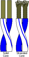
CAT-5 cabling can come with either "solid" or "stranded" cores. Each wire core in "solid" CAT-5 contains a single 24 gauge wire. Each wire core in "stranded" CAT-5 is made from several thin strands. The solid cable is stiffer and less suseptible to moisture contamination, making it the choice for in-wall wiring. The stranded cable is more flexible, less suseptible to fatigue from repeated bending and should only be used for cables no longer than 3 meters, making it the choice for patch cables (the cables connecting the wall jack to equipment). The connectors that are crimped on the end of CAT-5 are usually meant for either solid or stranded cable (though some will work with both), so be sure you get the right kind for your cable (and make sure they are CAT-5 rated).

CAT-5 cabling can also come "shielded" or "unshielded". All the wire pairs in "shielded" CAT-5 are contained in a wire-braid tube called a "shield". This further protects the wires from outside interference and reduces the amount of noise that can escape the cable. We recommend unshielded CAT-5 for home installations, and many equipment specifications also call for unshielded cables.

Another term you will hear a lot while shopping for CAT-5 cable is "plenum". "CAT-5 plenum" (sometimes called CMP) has the same performance characteristics as regular CAT-5 (sometimes called CMR, the "R" stands for "Riser"). The term "plenum" refers to the fire rating for the material making up the outer jacket of the cable. Plenum rated material does not release toxic fumes in the event of a fire. Regular CAT-5 uses a PVC jacket that will release toxic fumes when burned. Many building codes require the plenum for commercial installations but not for residential installations. Commercial buildings typically run cable through drop ceilings, and since the drop ceilings are also used for air circulation (this is called a "plenum space") there is the potential to distrubute fumes during a fire. Residential homes typically use sealed ducts to distribute air so there is no real chance for contamination (an exception to this is running wires in the return air space, which is typically not ducted). Also, homes are evacuated faster than commercial buildings, so the danger of a hazardous exposure to fumes is inherently less. With all the PVC already in most homes, in our non-expert opinion it is not worth the price difference to get plenum (sometimes twice as expensive), but that is a decision you should make for yourself after more carefull and thorough research. Refer to your applicable building codes regarding plenum cables before you make any installations.

There are other practical differences between CAT-5 cables. Some have a fiber filament that takes some of the tensil strain off the wires. Others have easier-to-distinguish colors on the wire pairs. These are just a few and it depends on the brand you buy.


CAT-5 Wire Pairs

The four wire pairs in a CAT-5 cable are distinguished by the color of their insulation. The four colors are (in order) blue, orange, green and brown. Thus, when refering to the "second pair" of wires, it is the orange pair. Regular phone cable consists of two untwisted pairs, each with wires of a different solid color (the first pair is Green/Red, the second is Black/Yellow). However, we will recommend CAT-5 for phone and concentrate there.

CAT-5 Wire Order
Pair # Wire Color Abbr. Wire #
(Pair)
Wire #
(Cable)
1 White/Blue W/B 1 1
Blue B 2 2
2 White/Orange W/O 1 3
Orange O 2 4
3 White/Green W/G 1 5
Green G 2 6
4 White/Brown W/Br 1 7
Brown Br 2 8

Strictly speaking, each colored pair consists of (in order) a white wire with a colored stripe and a colored wire with a white stripe. However, the rules for cables with so few pairs are lax. Most often you will find the pairs consisting of a white wire with a colored stripe and a solid colored wire. Sometimes the white wire may not even have a stripe (it may have dots or just be associated by the color of the wire it's twisted with), and sometimes it's not even white (being gray or transparent). Some cable has all solid colors in untwisted pairs (avoid completely as it is not CAT-5 rated). We will use the common white-striped/solid scheme throughout this site.

The table at right shows the order of the wire pairs. The color standard covers cables with more than four pairs, but that is out of the scope of this discussion.


CAT-5 Connectors

Phone and network connections both use a "Registerd Jack" (RJ) type connector. Phones use RJ-11 connectors, networks use RJ-45 connectors, which are a bit wider. The RJ type connectors are often called "modular connectors". Traditionaly when working with modular connectors, the hook will be underneath and the contacts (pins) will be on top. The diagrams below and the wall jacks follow this standard.
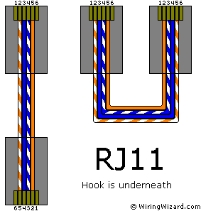
Figure 1: RJ-11
Click on picture to switch cable types
 
Figure 2: RJ-45
Click on picture to switch standards

Typical phones use 4 or 6 pin RJ-11 connectors (see Figure 1 at left). Most phone cables have four wires, but most phones only use the middle two. Click on the picture to switch between CAT-5 and regular phone cable. Although they look physically straight in Figure 1, phone cables are logically "crossed".

Bad RJ
(Click)

Wires in RJ-11 connectors do not follow a linear order (left-to-right), instead they follow a centric order, working from the center pins out (see Figure 1). To make connections compatable with both ends of a logically "crossed" cable, it is necessary for every pair in the cable to have each wire equidistant from the center of the connector (either that or every cable would have to have all 6 wires, a big waste). For example, if you have a cable with only one pair and it is at pins 1 & 2 at one end and 5 & 6 at the other, the cable would not work if the ends were unplugged and reversed because pins 1 & 2 would then be empty (click on picture at right).

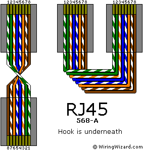
Network and ISDN cables use 8 pin RJ-45 connectors which look the same as RJ-11s, only a little wider (see Figure 2 at left). There are two standards for wiring RJ-45 connectors, called "568-A" and "568-B" for short, that differ on where pair 2 & pair 3 are pinned. Click on the picture to switch between the standards. Although they look physically crossed in Figure 2, network and ISDN cables are logically "straight".

Wires in RJ-45 connectors have a mix of centric and linear ordering. The two middle pairs are centric ordered, the two outer pairs are in linear order. To further confuse, the two standards swap where pair 2 & pair 3 go. When wiring an RJ-45 connector, first come the centric pins; pair 1 is on the middle pins (4 & 5) for both standards. The next pins out (3 & 6) will either be pair 2 (568-A) or pair 3 (568-B). Then come the linear pins; 1 & 2 will either be pair 3 (568-A) or pair 2 (568-B), and finaly pair 4 is on pins 7 & 8 for both standards. See Figure 2.

Note that for the RJ-11 and both RJ-45 standards, the wires will alternate between white-striped and solid-colored. When crimping on a modular connector, you should never get two white-striped wires next to each other, nor should you get two solid-colored wires next to each other. This is important to remember when pinning pair 1 (blue) whose second wire (solid-color) is pinned before it's first (white-striped).


568-A vs 568-B

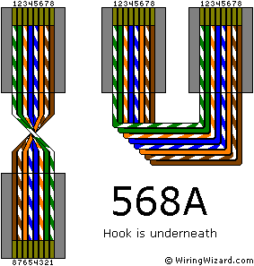
Figure 3: RJ-45, 568-A Standard
Click on picture to hide/show unused wires

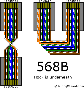
The two standards reverse where pair 2 (orange) & pair 3 (green) are pinned. As it happens, these are the only wires that are used in network cables. Network protocol does not use pair 1 (blue) or pair 4 (brown). You can click on the pictures to hide and show the unused pairs. ISDN cables use all four pairs.

Both standards are completely compatible with all network and ISDN equipment and each other. You can plug a 568-A cable into a 568-B jack. The only difference is the insulation color of the wire the signals will travel, and electrons don't care about that. As long as both ends of a cable are wired to the same standard, the cable will work.

We recommend the 568-A standard because it is similar to the wiring for an RJ-11 connector. Notice that the 4 middle wires in the 568-A figure to the right are the same as the 4 wires in the RJ-11 figure above. In the 568-B figure below, only the middle 2 wires match the middle 2 wires in the RJ-11 figure.

Figure 4: RJ-45, 568-B Standard
Click on picture to hide/show unused wires

The RJ-11/568-A similarity is beneficial because both phone and network cables will be terminated with an RJ-45 connector (CAT-5 will be used for both services) in the wiring closet before identifing each cable. We will then identify each cable by plugging in a wire tester to each cable. If both cable types are wired to the same standard, testing will be easier with less re-crimping. Another benefit is a cable can later be changed from phone to network (or vice versa or to both) with less confusion and work in keeping the colors correct.

The drawback is most off-the-shelf equipment is wired to the 568-B standard. The Leviton jacks have a pin designation for both the A and B standards. However, the CAT-5 patch panel that we will use to distribute the phone service is usually marked for one standard or the other. 568-B patch panels are common and will work just fine, but since we wire the RJ-45 connectors using 568-A, the orange wire would mate with the green posts on the panel and vise versa. A simple solution is to use paint pens and recolor the posts on the patch panel. Finding a 568-A patch panel will be more difficult, but having a patch panel that is marked in the same standard that you are wiring is worth the hassle.


Crossed vs. Straight Cables

Crossed Cables
PinPin
16
25
34
43
52
61

Phone cables are logically "crossed". A pin on one end of a crossed cable does not lead to the same pin on the other end. Instead, it leads to it's mirror opposite on the other end. When you hold the two ends of a phone cable in the same direction, one is wired in the reverse sequence of the other (see Figure 1 above). This is not the same as a "cross-over" cable for direct computer-to-computer connections as discussed below.

Figure 1 above and the table on the right show where a pin on one end of a crossed cable leads to on the other end. The same concept also applies to phone cables with only 4 or 2 wires.

Note that the concept only applies to male-male (cords) and female-female (couplings) phone cables. For male-female cables (splitters and extensions) the cable is not crossed but is logically 'straight' as described below.

Straight Cables
PinPin
1T+1T+
2T-2T-
3R+3R+
4 4 
5 5 
6R-6R-
7 7 
8 8 

Network and ISDN cables are logically "straight". A pin on one end of a straight cable always leads to the same pin on the other end. When you hold the two ends of a network cable in the same direction, both are wired in the same sequence (see Figure 2 above).

Figure 2 above and the table on the left show where a pin on one end of a straight cable leads to on the other end.

Network and ISDN cables are logically straight whether they have same-gender or opposite-gender ends.

To further add to the confusion, a logically crossed cable can physically lay flat (looking very straight) when put on a table with the hook underneath at both ends (see Figure 1 above). A logically straight cable must be physically twisted 180 degrees (looking very crossed) to lay on a table with the hook underneath at both ends (see Figure 2 above).

The good news is that the phone wiring discussed in this site will deal entirely with logically straight cables. We will use RJ-45 connectors (male) on the end in the wiring closet and wall jacks (female) on the other, so the cables can be thought of as 'extensions'. So why bring all this up you ask? Just in the name of completeness.
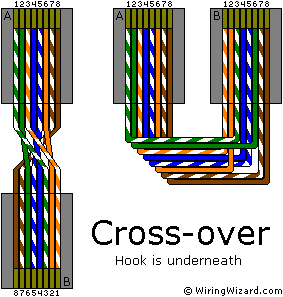

Cross-over Cables

Figure 5: Cross-over Cable
Click on picture to hide/show unused wires

Two computers can be connected directly using a "cross-over" cable. This is not the same as a "logically crossed" cable as discussed above. A cross-over cable swaps the transmit and receive pairs between the ends. In this configuration, the transmit pins on one computer are directly connected to the receive pins on the other. The unused pairs are wired normally. Click on the picture to hide and show the unused wires.

Cross-over Cables
PinPin
1T+3R+
2T-6R-
3R+1T+
4 4 
5 5 
6R-2T-
7 7 
8 8 

Figure 5 at right and the table on the left show where a pin on one end of a cross-over cable leads to on the other end.

A subtle but helps-you-remember-how-to-do-it result of this swaping is that one end is wired 568-A, the other is wired 568-B.


All contents and scripts copyright © 2000, WiringWizard.com